Fuses: Difference between revisions
Jump to navigation
Jump to search
mNo edit summary |
mNo edit summary |
||
| Line 13: | Line 13: | ||
=== Under bonnet fuses === | === Under bonnet fuses === | ||
The engine bay fuse box contains both the common blade-type fuses, as well as some heavy-duty fuses rated from 30A to 150A. Although most of these pull straight out, the four large fuses on the left side in the picture are bolted in both from the front and back. This includes eg the 150A alternator fuse, which is typically damaged (along with other items) if someone attempts to jump-start the vehicle with power connected the wrong way. | The engine bay fuse box contains both the common blade-type fuses, as well as some heavy-duty fuses rated from 30A to 150A. Although most of these pull straight out, the four large fuses on the left (drivers) side in the picture are bolted in, both from the front and back. This includes eg the 150A alternator fuse, which is typically damaged (along with other items) if someone attempts to jump-start the vehicle with power connected the wrong way. | ||
To remove and replace eg the 150A alternator fuse: | To remove and replace eg the 150A alternator fuse: | ||
| Line 20: | Line 20: | ||
# Remove the cover of the fuse box using a large screwdriver (or a suitably sized coin) | # Remove the cover of the fuse box using a large screwdriver (or a suitably sized coin) | ||
# Gently fold the red plastic ‘shield’ so that the vertical bolt is exposed and can be removed | # Gently fold the red plastic ‘shield’ so that the vertical bolt is exposed and can be removed | ||
# Unclip the front row of fuses, | # Unclip the front row of fuses, thus providing access to the rear bolts | ||
# Unscrew front and rear bolts to the | # Unscrew front and rear bolts to the applicable fuse(s) | ||
# In principle, the fuses can now be pulled straight | # In principle, the fuses can now be pulled straight out | ||
# However, the old plastic is brittle and the fuses may be stuck | # However, the old plastic is brittle and the fuses may be stuck | ||
# If so, release the pressure on the other bolts clamping the metal brackets | # If so, release the pressure on the other bolts clamping the metal brackets | ||
| Line 33: | Line 33: | ||
[[File:Good and Bad 150A fuses.jpg|thumb|Good and Bad 150A fuses]] | [[File:Good and Bad 150A fuses.jpg|thumb|Good and Bad 150A fuses]] | ||
[[File:Front row of fuses unclips.jpg|thumb|Front row of fuses unclips (after removing vertical bolt under red plastic ‘+’ shield)]] | [[File:Front row of fuses unclips.jpg|thumb|Front row of fuses unclips (after removing vertical bolt under red plastic ‘+’ shield)]] | ||
[[File:Four fuses are bolted in.jpg|thumb|Four fuses are bolted in]] | [[File:Four fuses are bolted in.jpg|thumb|Four fuses are bolted in, both from front and back]] | ||
[[File:Fuse box metal plates can be removed.jpg|thumb|Fuse box metal plates]] | [[File:Fuse box metal plates can be removed.jpg|thumb|Fuse box metal plates]] | ||
You will need 8mm, 10mm, 12mm and 14mm sockets. | |||
Latest revision as of 13:41, 11 June 2023
Location
Fuses are located in two locations:
- in the cabin, on the drivers side footwell wall (above the drivers right knee)
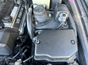
- in the engine bay, on the passenger side behind the battery (protected by a black plastic cover)
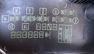
Diagram of fuse box layout
Under bonnet fuses
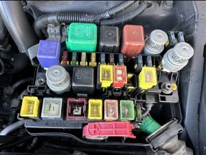
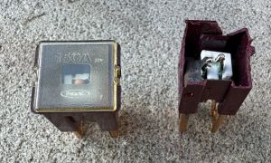
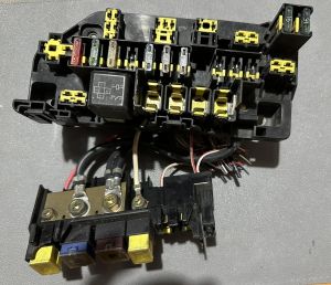
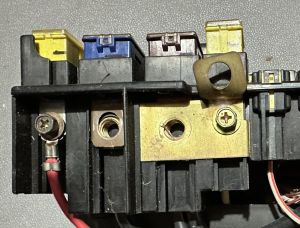
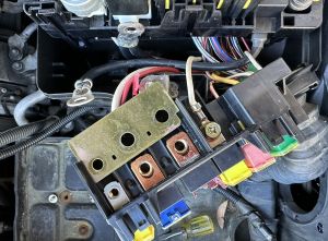
The engine bay fuse box contains both the common blade-type fuses, as well as some heavy-duty fuses rated from 30A to 150A. Although most of these pull straight out, the four large fuses on the left (drivers) side in the picture are bolted in, both from the front and back. This includes eg the 150A alternator fuse, which is typically damaged (along with other items) if someone attempts to jump-start the vehicle with power connected the wrong way.
To remove and replace eg the 150A alternator fuse:
- Disconnect the battery (to avoid further electrical issues, and also to free up access)
- Remove the cover of the fuse box using a large screwdriver (or a suitably sized coin)
- Gently fold the red plastic ‘shield’ so that the vertical bolt is exposed and can be removed
- Unclip the front row of fuses, thus providing access to the rear bolts
- Unscrew front and rear bolts to the applicable fuse(s)
- In principle, the fuses can now be pulled straight out
- However, the old plastic is brittle and the fuses may be stuck
- If so, release the pressure on the other bolts clamping the metal brackets
- If necessary, fully remove these bolts and remove the metal bracket
- The fuses can now be more easily pushed out from the bottom with minimal pressure
You will need 8mm, 10mm, 12mm and 14mm sockets.

