On-board diagnostics
The UZZ32 Soarer features on-board diagnostics which can assist in troubleshooting. Various ECUs watch for eg sensor errors and store relevant error codes for retrieval. The user can then lookup the error code to help understand and address the cause.
The process for using the on-board diagnostic is, in summary:
- Clear pre-existing error codes
- Enable test mode
- Test drive the vehicle
- View the error codes
Clearing error codes
Since error codes are not automatically cleared (nor time-stamped), it is recommended that you clear any existing error codes before proceeding with the diagnostics. Otherwise, you are likely to be confused by old error codes that are likely to be irrelevant either because the issues have since been resolved or were false-alarms to start with.
The options for clearing the error codes are:
- Remove the EFI fuse (the 30A fuse located in the under-the-bonnet fuse block)
- Disconnecting the battery
Power needs to be removed for 10 seconds to ensure that the error codes are cleared.
Entering Diagnostic Mode
To enter diagnostic mode:
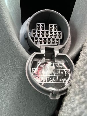
- Locate the DLC1 connector (under the bonnet) or DLC2 connector (under the dash) and flip up the cover
- If using DLC1, remove the bridging pin between WA and WB
- Bridge the appropriate ports (eg TC and E1 ports) using eg a piece of wire:
- TC -> E1 for main diagnostics and/or TS -> E1 for suspension diagnostics
- TE1 -> E1 for engine (etc) check
- TE2 -> E1 for "high sensitive mode", recommended if having received errors ___, ___ or ___.
- Turn the ignition on and check the dash to ensure that test mode is active
Alternatively, the diagostic mode can be entered through the EMV by:
- pressing the top-right and bottom-right buttons on the EMV (for x seconds?)
Test Drive
The purpose of the test drive is not just to replicate the error conditions, but also to ensure that the appropriate sensors are activated. Consequently, the test drive should include:
- Open the door
- Press 'all' the switches (Suspension Height, ECT Mode, TRC, Overdrive, Autodrive/Cruise Control, Suspension on/off)
- Drive > 25 km/hr
- Stop the vehicle
If the test drive does not include the above, you should receive error codes indicating, eg, that the wheels have not turned.
Viewing Diagnostic Codes
There are four different ways to view the error codes:
- though the dash
- through the EMV
- by connecting a Toyota / Lexus test tool
- by connecting a test light or voltmeter to the diagnostic port
Viewing error codes on the dash
- While in diagnostic mode, press the Scroll button on the dash
- This cycles through the available systems (eg ___, ___, ____ and ____) and displays either <System> OK or <system> NG (No Good), eg TRC OK, ABS NG etc.
- If a component is shown as NG, stay on that screen and the dash will start scrolling through the various error codes, eg ABS 21 ABS 22 etc. This may take a couple of minutes.
- The error codes will be displayed in increasing order and end with a [] on the dash
Viewing error codes on the EMV
The EMV will also display error codes, but the systems available from the EMV differ. Eg, it will display errors for EFI, but not the suspension. It does however display errors for the TV, Navigation, CD-ROM etc.
Viewing error codes through a test tool
Toyota / Lexus would have test tools available (at least in Japan) that can directly decode the errors via the diagnostic port.
Connecting a volt-meter or test light to the DLC
While in test mode, the error codes can be accessed via the W pin in the DLC. Connect a light-bulb, volt-meter or LED from B+ (Battery) to the W pin, and count the flashes. If using a LED, be sure to also add a resistor in series.
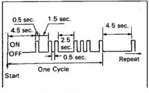
The code consist of short (0.5 seconds) pulses representing the number, a short (1.5 seconds) break between each pulse, and a longer (2.5) seconds break between the tens of numbers and the actual numbers. At the end of the transmission, there will be a longer (4.5 seconds) break before the patterns repeat.
If there are no error codes, the signal will be a repating on-off at regular (0.25 seconds) intervals.
Looking up the error codes
The meaning of the respective error codes can be looked up in the manuals as well as on many websites. Some codes are common to various Toyota / Lexus vehicles, while others have a specific meaning on the UZZ32.
Connectors
There are two diagnostic ports on the UZZ32:
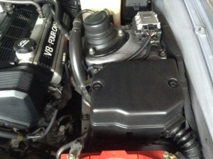
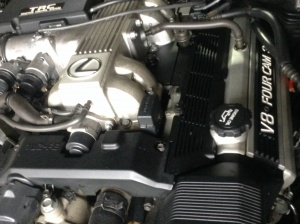
- DLC1 is the rectangular port on top of the engine
- DLC2 is the circular port in the vehicle cabin
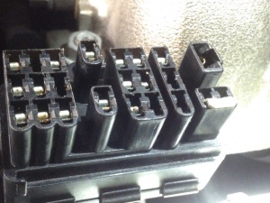
Each port has multiple pins, some (but not all) of which exist on both connectors. The inside of the lid covering each connector has a diagram showing the pin locations. Please also note that some pin locations may potentially be empty (ie there is a spot for a pin, but no metal connector). This might also vary depending on the year of manufacture.
Pins that are potentially useful include:
- OX1 - Oxygen sensor value: Volt = 0.1 - 0.4 = Lean, 0.4 - 0.7 = normal, 0.7 - 0.9 v = Rich
- AB - used for resetting the Airbag warning light
- IG - ignition pulse, eg RPM indicator
- OP2 and OP3 = K & L Diagnostic lines
- OPI - Immobiliser (not used on early 1UZFE-engined vehicles such as the UZZ32)
- TT - Transmission
- FP = Fuel Pump
- E1 = Earth
- B+ = Battery power
- VF1 and VF2 = Lambda (Oxygen sensor?)
- TS = Speed sensors for ABS and TRC
- TE2 = High-sensitivity test mode
- TC = ABS, Airbag, Height Control, TRC, Cruise
Protocols
The UZZ32 Soarer uses a pre-cursor to OBDII. Hence, OBDII scan tools will not work.
References
- Soarer Central: Running V8 & 3 Litre Engine Diagnostics. (Applies to TT as well) - http://soarercentral.com/sc-forum/messages/1113/862.html?1100787369
- Soarer Central: OBD scan tool - http://soarercentral.com/sc-forum/messages/282/350195.html
- This is how you wire up a 1UZ-FE Engine.pdf - Google Drive - https://drive.google.com/file/d/0B0WE7dVhvJd_UFRKeEptSTVqaTg/edit?pli=1
- How to Wire up a 1UZ engine (VVTI and non-VVTI) - Club Lexus Forums - http://www.clublexus.com/forums/build-threads/754842-how-to-wire-up-a-1uz-engine-vvti-and-non-vvti.html
- Lexus LS400: How to Read & Clear Diagnostic Trouble Codes - http://www.lexls.com/tutorials/intro/codereading.html
- Diagnostic port. - http://www.soarerworld.com/forum/showthread.php?6013-Diagnostic-port
- How to do a diagnostic check. - http://www.soarerworld.com/forum/showthread.php?28928-How-to-do-a-diagnostic-check
- Planet Soarer: My Soarer won't start - why OBD is your friend - http://planetsoarer.com/obd/obd.htm
- Diagnostic sockets and tests you can run - Lextreme: Lexus-Toyota V8 Forum - http://www.lextreme.com/forums/showthread.php?t=1323
- Lexus LS400: How to Read & Clear Diagnostic Trouble Codes - http://www.lexls.com/tutorials/intro/codereading.html
- Soarer testing oxygen / lambda / o2 sensors | Soarer Union and JZX Nation - http://forum.soarerunion.com/index.php?threads/soarer-testing-oxygen-lambda-o2-sensors.868/
- How can you tell which protocol your vehicle uses? - https://www.scantool.net/forum/index.php?PHPSESSID=bf8okdd0nvo10lvu39n5ee2e11&topic=2840.0
- Lexus OBD Trouble Codes - http://www.troublecodes.net/lexus/
- Toyota old diagnostic connector pinout diagram @ pinoutsguide.com - http://pinoutsguide.com/CarElectronics/Toyota_old_diagnostic_pinout.shtml
- Information: Vf - http://www.supramania.com/forums/showthread.php?39856-Information-Vf
- Soarer Central: Full ECU circuit (schmatic) diagram for 1uz-fe - http://soarercentral.com/sc-forum/messages/282/383632.html
