Field AH-5 Height Controller for UZZ31: Difference between revisions
Jump to navigation
Jump to search
No edit summary |
No edit summary |
||
| Line 41: | Line 41: | ||
* http://www.alscarchive.com/cgi-bin/discus/discus.cgi?pg=prev&topic=3&page=50270 | * http://www.alscarchive.com/cgi-bin/discus/discus.cgi?pg=prev&topic=3&page=50270 | ||
* http://soarercentral.com/sc-forum/messages/30604/386652.html?1428138901 | * http://soarercentral.com/sc-forum/messages/30604/386652.html?1428138901 | ||
* http://www.soarerworld.com/forum/showthread.php?15230-need-a-cd-unit/page2 | |||
Revision as of 13:22, 4 April 2015
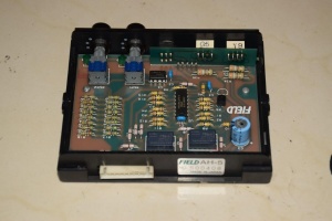
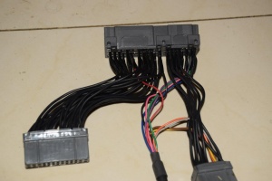
Although 3rd party height controllers such as the Field AH-5 are readily available for UZZ31 Soarers, they do not appear to be compatible with UZZ32 Soarers.
Error creating thumbnail: Unable to save thumbnail to destination
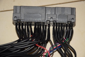
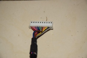
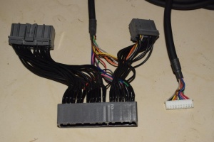
Wiring appears to consist of:
- 4 inputs
- 4 outputs
- power
- ground
Power and ground pins are spliced into the existing circuit. The others appear to be a case of diverting the 4 x sensor inputs into the controller and then sending the (modified) values into the Soarer's suspension controller.
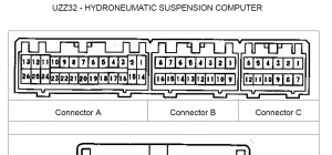
- PIN B2 (Purple wire) - SHFR = Suspension Height Front Right ?
- PIN B3 (Pink wire) - SHRR = Suspension Height Rear Right ?
- PIN B10 (Green wire) - SHFL = Suspension Height Front Left?
- PIN B11 (Blue wire) - SHRL = Suspension Height Rear Left ?
- PIN A14 (Black wire) - assumed to be earth but does not seem to match with diagram
- PIN A8 (Red wire) - assumed to be ignition but does not seem to match with diagram
All other wires appear to be straight pass-through for connectors A and B, except for the handful of pins (A7, A18, A19, A21 and B4) that are not used. Connectors C and D are not used at all by this controller.
References that may assist those considering building their own controllers include:
- http://members.westnet.com.au/rbaird/SuspensionCodes.pdf
- http://planetsoarer.com/UZZ32/activecomputer.pdf
- http://www.alscarchive.com/cgi-bin/discus/discus.cgi?pg=prev&topic=3&page=50270
- http://soarercentral.com/sc-forum/messages/30604/386652.html?1428138901
- http://www.soarerworld.com/forum/showthread.php?15230-need-a-cd-unit/page2
